I wasn't entirely sure what to expect with a title like "enchanted objects." I know JK Rowling was inspired by some buildings in Glasgow, but I know this isn't Hogwarts, so I was very curious what this could possibly entail. Of course, what I found out over the span of the two days was that there is a sense of magic around this module, where we take seemingly normal objects such as LED lights and piezo buzzers, and add a little life to them. The tag line of the module is something along the lines of, "ordinary things made extraordinary," which piqued my interest, as I'm more of hands on learner.
Day 1 was a whirlwind of the Launch and Workshop 1. The launch was helpful because as much as the information about the assignment especially is available, it's always nice to have it broken down step by step. We learned about artists such as Yuri Suzuki, who uses the Ototo system to make sound art. One of the more interesting thoughts came from David Rose. He had this idea of "Terminal World," where the only options for human-computer interfacing are black slabs of glass, just in different size (for example, a phone, a tablet, and interaction ordering screen at a restaurant.) He is hopeful for a more positive experience, where physical objects are imbued with computational interactivity and are more useful than simply a piece of glass in your hand. Then there is the idea that having all of this interactivity may not being a good thing? And that's where, we as interactive designers, need to ask ourselves whether the object we're enchanting will end up being helpful or harmful and the future impact of what we are trying to accomplish. I also learned that graphite is conductive, which I just thought was so neat.
In Workshop 1, we went over what an Arduino actually is. Arduinos can be used independently or with the sketch written on a computer. Once a sketch is loaded onto an Arduino, it will run that sketch until it's reset. The version we're using is an R3, which isn't the newest, but it will be the most compatible with the sketches and programs we're using.

We went over all of the components of the Arduino, from what the digital pins are and what they do, to the microchip that does all the computing. We learned that there are two different types of circuits; a simple circuit would connect directly to the Arduino, whereas a more complex circuit would require the use of a Breadboard (which, in case anyone was wondering, is not, in fact, made out of actual bread). The Breadboard is good because it allows us to test circuits without having to solder anything, creating a more permanent connection.
The Arduino program is very similar to that of Processing in the sense that writing the codes starts off the same with void setup and void draw. The program is super smart, so much so that it predicts things like squiggly brackets, putting them in places it thinks it goes. I need to figure out how to shut that off because it's driving me nuts. Like Processing, Arduino runs in a loop of 60 times a second. Delays and timers are measured in milliseconds. If you wanted to run a longer timer, you'd need to use the long function which gives you greater range of times. There are a couple ways to get the Arduino to perform a function such as lighting an LED or sounding a piezo buzzer: push buttons and capacitive sensors. Push buttons work by being touched together, whereas the capacitive sensors function buy human touch.
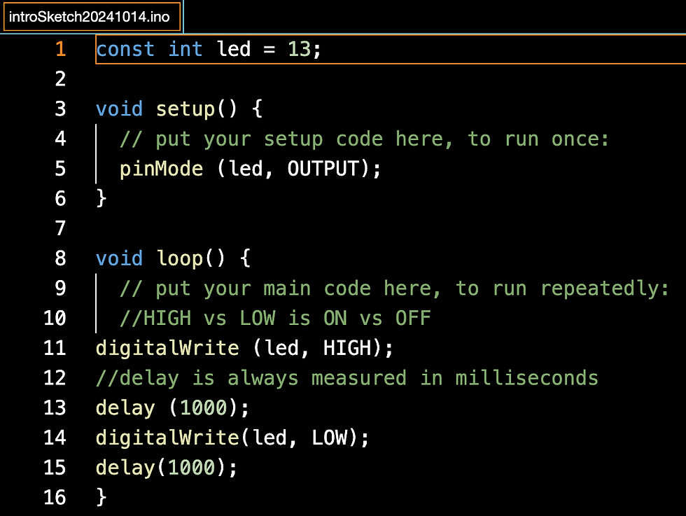
The first thing to do was set up a simple sketch with 1 LED. This ran the code through the computer directly to the Arduino, making the LED light up in a steady fashion.


Next, we started using capacitive touch sensors, starting with one, which when touched to the other, would light the LED, and stop when they weren't touched together.
Then we took it up a notch and added another sensor and another LED with the same idea of when the sensors were touching, they would light the LED, and stop when they weren't touched.


The last thing we did was to add a capacitive touch sensor which when touched would light the LED, and stop when released. The difference in setup between this and the last setup was the addition of the Mega Ohm Resistor which helps prevent component burn outs. I'll remember this because in rock climbing there is a device called an Ohm. Its purpose, in the simplest of terms, is that when a smaller climber is belaying a heavier climber, and the heavier climber falls, it slows the rate of descension therefor helping to protect the smaller climber. In this case, the small climber is the LED, and the big climber is the electricity. Analogies are great. Anyway, here's a capacitive touch sensor.


Comments